Saturday, 19 November 2016
Tuesday, 15 November 2016
Friday, 11 November 2016
Friday, 4 November 2016


Saturday, 9 April 2016
Friday, 4 March 2016
Tuesday, 23 February 2016
Wednesday, 10 February 2016
Arduino IR signal detector


Materials
- 10k Ohm resistor
- IR Phototransistor
- Hookup wire
Circuit Layout (refer to Drawing)
Simply connect the Phototransistor and Resistor in series.Connect the emitter pin of the Phototransistor (long leg) to GND and the collector pin (short leg) to the resistor which we will connect to the 5v pin of the Arduino.
Analog pin 0 needs to read the voltage drop across the Phototransistor so connect the A0 pin to the Phototransistor's collector pin.
Tuesday, 9 February 2016
Thursday, 4 February 2016
Components
Phototransistor (IR emitter)
high responsive one
Infrared LED
Resistor
Transistor 2N7000
MOSFET - is a type of transistor used for amplifying or switching electronic signals
high responsive one
Infrared LED
Resistor
Transistor 2N7000
MOSFET - is a type of transistor used for amplifying or switching electronic signals

Friday, 29 January 2016
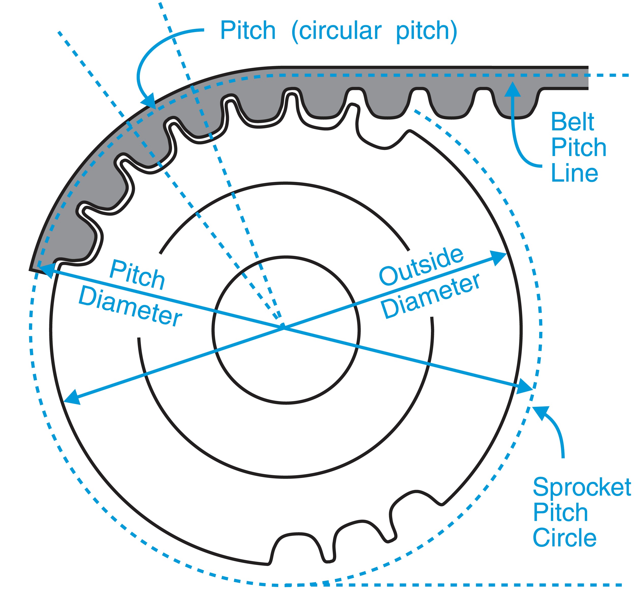
Timing Pulley System - velocity ratio
http://arab-training.net/vb/t4973.html


The diagram opposite shows a small driver pulley pulling round a larger driven pulley. The rpm (revolutions per minute) of the larger driven pulley wheel will be less than the smaller driver pulley wheel. The same principle regarding speed of rotation regarding gears applies to pulley systems as well.
WORKING OUT THE VELOCITY RATIO OF PULLEYS
The system shown above has a driver pulley attached to a motor. When the motor is switched on the driver pulley revolves at 20 rpm. The diameter of the driver pulley wheel is 200mm and the driven pulley wheel is 400mm. This means for every single revolution of the larger driven pulley wheel, the smaller driver pulley wheel rotates twice. This is due to velocity ratio. The ratio can be worked out mathematically in different ways. The two most likely methods are shown below
This means that the larger pulley wheel (the driven pulley wheel) revolves half as fast compared to the smaller driver pulley wheel. In effect the driven pulley wheel is slower and revolves half as many times as the driver. This means if the rpm of the driver pulley wheel is divided by 2, the output rpm of the driven pulley wheel will be found.


Tuesday, 26 January 2016
L298

The L298 is an integrated monolithic circuit in a 15- lead Multiwatt and PowerSO20 packages. It is a high voltage, high current dual full-bridge driver designed to accept standard TTL logic levels and drive inductive loads such as relays, solenoids, DC and stepping motors. Two enable inputs are provided to enable or disable the device independently of the input signals. The emitters of the lower transistors of each bridge are connected together and the corresponding external terminal can be used for the connection of an external sensing resistor. An additional supply input is provided so that the logic works at a lower voltage.
**give the drive voltage to power the motor's voltage
Can test IN1, IN2, ENA by using electrometer. connect one end to the legs of L298 and the other side to the 8 pins.
ENA usually at the back
IN1 and IN2 are at the left bottom side.
Connect VCC to positive to a transformer
Connect GND with arduino and transformer
IN1 and IN2 to arduino
ENA to ~PWM


Sunday, 24 January 2016
Coaxial power connector

The outer contact is generally called the barrel, sleeve or ring, and the inner contact is called the tip.
Thrust bearing
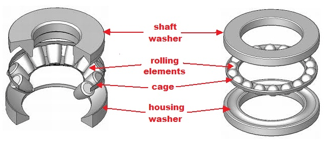
to support a predominately axial load
Side Story ^^
Fluid-film thrust bearings were invented by Australian engineer George Michell They were used extensively in ships built during World War I. :)
Fluid-film thrust bearings were invented by Australian engineer George Michell They were used extensively in ships built during World War I. :)
Torque
Torque is a measure of "twisting force".
Power is a measure of twisting force x speed.
Power is a measure of twisting force x speed.
Torque is usually expressed as a Force x a distance So for the same Torque if you double the distance you halve the force to get the same answer.
So kg.cm is kg force x centimetre distance.
In fact kg are a mass and not a force BUT kg are sloppily used as a force in many cases.
In fact kg are a mass and not a force BUT kg are sloppily used as a force in many cases.
In your case 3 kg.cm means that a "force" of 3 kg acting at a radius of 1 cm would produce the same amount of torque as your motor.
Equally that could be 0.1 kg x 30 cm, or 10 kg x 0.3 cm or ...
Equally that could be 0.1 kg x 30 cm, or 10 kg x 0.3 cm or ...
A motor with 1 kg.cm torque is capable of holding a 1 kg weight at a radial distance of 1 cm.
Here is a diagram to explain.

Torque is the cross-product of force and distance: . So the same weight, at twice the radial distance, will require double the torque.

Note that the measurement 'kgcm' is 'kilograms-force × centimetres' and would be clearer if written as , which avoids confusion between kg (mass) and (force.)
Subscribe to:
Comments (Atom)